
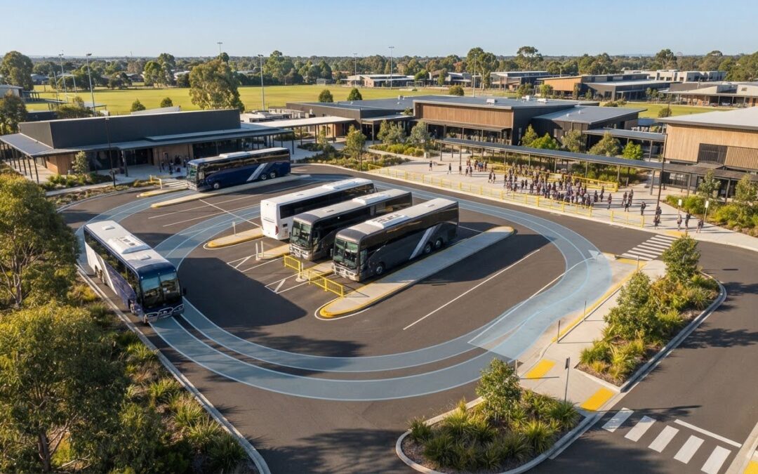
Standard school drop-off zones are fundamentally incapable of accommodating 12.5 to 14.5-metre charter coaches. Proper bus bay design for school excursions requires far more than extending a standard passenger kerb; it demands heavy vehicle geometry and clear pedestrian isolation. You already understand the friction of excursion mornings, where multi-coach arrivals conflict with parent traffic, bottleneck internal circulation, and trigger development application refusals due to deficient swept paths and conflicting regulatory standards.
Securing council approval demands clarity on the exact geometric, safety, and technical parameters for commercial passenger vehicles. In this engineering guide, you’ll learn the precise standards required to design compliant excursion facilities that withstand regulatory assessment. We detail the operational distinctions between AS 2890.2 and Austroads guidelines, swept path validation methods, and multi-coach staging layouts that keep student groups safely separated from live roadway networks.
Key Takeaways
- Charter coaches measuring up to 14.5 metres demand specific heavy vehicle spatial geometry that standard car drop-off loops cannot accommodate.
- Compliant bus bay design for school excursions relies on synthesising AS 2890.2 commercial facility criteria with Austroads roadway and pedestrian planning principles.
- Selecting between parallel, indented, and saw-tooth bay layouts establishes physical segregation between large student marshalling groups and parent traffic queues.
- Validating ingress, egress, and internal circulation with computerised swept path analysis eliminates geometric clashes before lodgement.
- Comprehensive Traffic Impact Assessments resolve council safety concerns upfront, establishing a direct pathway to development application approval.
Understanding Excursion Bus Bay Design Requirements for Australian Schools
Standard transport planning frameworks often treat school passenger zones as routine, short-stay transit stops. While a conventional roadside bus turnout accommodates brief passenger boarding within a two-minute window, excursion logistics operate under entirely different operational demands. Proper bus bay design for school excursions requires dedicated heavy vehicle geometry to manage multi-coach arrivals, prolonged dwell times, and concentrated groups of students moving simultaneously.
To review the geometric and operational differences between basic stops and dedicated passenger bays, watch this engineering overview:
Charter Coaches Versus Daily School Bus Operations
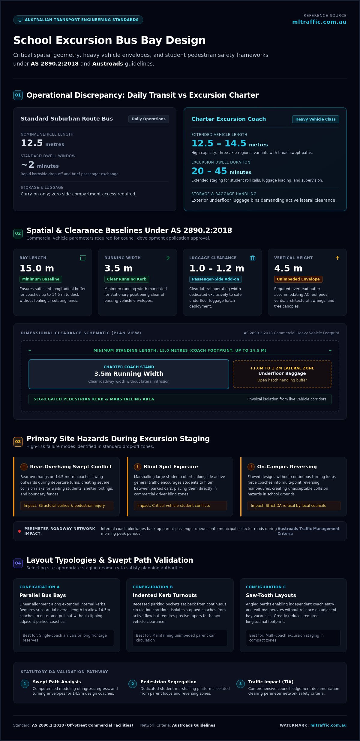
Suburban route buses clear kerbside space rapidly. Conversely, charter coaches dwell for 20 to 45 minutes to facilitate roll calls, underfloor luggage loading, and coordinated boarding. Standard urban buses measure approximately 12.5 metres in length. High-capacity charter coaches, particularly three-axle regional variants, extend up to 14.5 metres. These larger vehicles feature wide sweeping paths and substantial body overhangs that demand greater kerb length and storage capacity than daily school bus infrastructure provides.
Primary Safety Risks During School Excursion Staging
Combining heavy charter vehicles with high-density student activity introduces critical site hazards that standard car parks cannot mitigate:
- Rear-overhang swept path conflicts: Long rear overhangs on 14.5-metre coaches swing outwards during departure turns, creating severe impact risks for waiting students, shelter footings, and boundary fences.
- Pedestrian blind spot exposure: Marshalling large classes adjacent to general traffic lanes leads to students filtering between parked cars, placing them directly within driver blind spots.
- Reversing hazards on campus: Flawed layouts without dedicated turning loops force drivers into multi-point reversing manoeuvres. Within an active school environment, reversing heavy passenger vehicles generates unacceptable collision risks.
Flawed bus bay design for school excursions also leads to site-wide bottlenecks. If coaches obstruct internal circulation roads, parent passenger vehicles back up onto surrounding collector streets, compromising municipal road networks during morning peak periods.
Australian Standards and Design Guidelines for School Bus Facilities
Achieving statutory planning consent for educational institutions requires strict alignment with national road design standards. While municipal authorities evaluate traffic impacts on perimeter networks using the Austroads Guide to Traffic Management, on-site heavy vehicle arrangements must satisfy AS 2890.2:2018 (Parking facilities – Part 2: Off-street commercial vehicle facilities). Integrating these frameworks ensures bus bay design for school excursions withstands rigorous engineering scrutiny during council assessment.
Key Dimensions and Clearances Under AS 2890.2
Standard municipal road manuals rarely cover the unique spatial footprint of long-distance tour coaches. AS 2890.2 governs commercial vehicle loading areas, establishing hard geometric baselines for site planning:
- Bay Length: A single-unit coach bay requires a minimum standing length of 15.0 metres. This footprint provides sufficient longitudinal buffer for coaches up to 14.5 metres to dock without obstructing adjacent circulating lanes.
- Bay Width: Bays must provide a minimum running width of 3.5 metres. Long-distance excursion coaches feature exterior luggage bins, which require an additional 1.0 to 1.2 metres of clear lateral operating width on the passenger side for safe baggage handling.
- Vertical Clearance: Off-street coach zones mandate an unimpeded overhead envelope of at least 4.5 metres, accounting for air conditioning pods, roof hatches, tree canopies, and architectural awnings.
Where site layouts restrict heavy vehicle circulation, reviewing preliminary footprints through professional Car Park Design ensures geometry complies with national commercial standards prior to formal submission.
Austroads Geometric Guidelines and Road Reserves
Bus facilities directly interfacing with public road networks fall under Austroads Guide to Road Design criteria. When coaches diverge from through-traffic lanes, deceleration tapers must provide sufficient length for heavy vehicles to reduce speed without disrupting upstream traffic flow. Similarly, acceleration tapers and entry kerb radii require generous dimensioning; inadequate turning radii force coaches to straddle centreline markings, sweeping over opposing lanes during departure turns.
Site engineers must also coordinate these geometric baselines with statutory building codes and accessible transport policies. Safe bus bay design for school excursions demands generous, grade-separated pedestrian paths alongside the kerb, preventing passenger crowds from spilling into active travel carriageways while bags are loaded.
Comparative Layout Configurations for School Bus Bays
Site topography, property boundaries, and peak traffic volumes dictate the structural layout of heavy passenger vehicle infrastructure. While standard guidelines often default to basic linear kerbsides, multi-coach excursion operations require strategic geometric solutions to prevent site-wide gridlock. Choosing the right layout balances land consumption against operational efficiency and student protection.
Indented Kerbside Bus Bays
Positioned directly within the public road reserve, indented bays preserve valuable campus land. They require substantial entry and exit tapers, typically consuming up to 50 metres of total linear street frontage per bay to allow smooth vehicular transitions. A critical limitation remains coach sequencing. In an indented linear bay, coaches must depart in the exact order they arrive unless wide overtaking bypass lanes are constructed alongside them.
Dedicated Off-Street Internal Bus Loops
Dedicated off-street loops route heavy vehicles away from public commuter corridors entirely. Moving coach operations inside the property boundary eliminates perimeter road queues during major excursion departure windows. These loops allow educators to marshal students within secure school grounds, isolating them from public traffic networks. To function efficiently, they must operate via strict one-way circulation systems with adequate turning radii, preventing internal blockages between coach movements and staff parking.
Sawtooth Bus Staging Bays
Angled or sawtooth configurations deliver distinct operational benefits when multiple classes depart simultaneously:
- Independent departures: Coaches can pull in and out of assigned berths independently, eliminating delays caused by late-boarding groups blocking an entire queue.
- Linear footprint reduction: Angled parking compresses the necessary street or campus frontage compared to long, continuous parallel kerbs.
- Defined pedestrian zones: Sawtooth kerb designs create natural physical barriers that channel students directly toward the front passenger door, keeping them well clear of rear blind spots.
Despite these benefits, sawtooth bays require wider internal drive aisles, often measuring 12 to 15 metres, to give 14.5-metre coaches sufficient room to manoeuvre into position. Evaluating operational needs upfront ensures the chosen bus bay design for school excursions satisfies both educational logistics and local council development standards.
Step-by-Step Technical Design and Swept Path Workflow
Static vehicle turning templates can’t replicate dynamic heavy coach behaviour in tight school environments. Delivering certifiable bus bay design for school excursions requires a systematic CAD modelling process. By testing exact vehicle envelopes against physical site constraints early, engineering teams eliminate costly layout revisions during council review.
Step 1: Establishing Design Vehicle Parameters
Every engineering workflow begins by selecting the appropriate design vehicle envelope from national standards libraries. A standard 12.5-metre heavy rigid bus provides the absolute baseline for standard operations. However, excursion facilities require testing against a 14.5-metre three-axle charter coach to accommodate long-distance interstate carriers. When schools hold established partnerships with specific operators, engineers extract exact manufacturer chassis configurations, wheelbases, and front and rear overhang measurements to model authentic operational clearances.
Step 2: Performing Computerised Swept Path Analysis
Engineers run dynamic vehicle simulation software like AutoTURN to model realistic forward movements, turn transitions, and reversing manoeuvres within the proposed footprint. The simulation models tire tracks alongside total swept body envelopes, capturing critical tail swing. Review the following clearance standards during assessment:
- Kerb Clearances: Maintain an absolute minimum operating clearance of 300 millimetres between the vehicle wheel path and raised kerbs.
- Vertical Infrastructure Buffers: Ensure a minimum lateral buffer of 500 millimetres between the vehicle body overhang envelope and physical assets like awnings, lighting columns, and signposts.
- Continuous Forward Ingress and Egress: Eliminate the need for multi-point reversing maneuvers across student marshalling zones.
Executing professional Vehicle Swept Path Analysis early identifies spatial bottlenecks and ensures turning envelopes pass statutory planning assessments on first submission.
Step 3: Designing Pedestrian Containment and Marshalling Areas
Once vehicle swept paths are established and locked, engineers design the pedestrian holding platform. Waiting platforms require a continuous clear width of at least 3.0 metres to contain entire classes with backpacks without crowding the roadway edge. Installing physical balustrades channels students away from the coach front wheel trajectory and toward signalised or zebra crossings. Kerb zones must also incorporate continuous tactile ground surface indicators and accessible pram ramps, maintaining full compliance with national disability transport standards while preserving uninterrupted sightlines between the seated coach driver and standing children.
Council Development Applications and Professional Traffic Engineering Services
Modifying school access infrastructure triggers formal planning scrutiny from local government authorities. School campuses generate significant traffic volumes during morning and afternoon peaks. When institutions introduce or reconfigure bus zones, council assessment teams focus on neighbourhood safety, intersection performance, and public right-of-way congestion. Rudimentary concept sketches will not satisfy development application requirements; councils demand certified engineering documentation confirming adherence to statutory standards.
Traffic Impact Assessment Reports for Educational Facilities
A formal Traffic Impact Assessment (TIA) Report provides the empirical evidence councils require to determine an application. Rather than evaluating heavy passenger facilities in isolation, an expert assessment examines overall site operations during excursion staging periods:
- Trip Generation and Distribution: Quantifies peak arrival and departure movements generated by multi-coach operations alongside standard morning parent traffic.
- Intersection Capacity and Queuing: Evaluates adjacent intersections using SIDRA modelling to confirm coach access will not lead to excessive queues or block public collector roads.
- Sight Distance Validation: Confirms driveway sight triangles satisfy Australian Standards, ensuring coach drivers exiting the property possess unobstructed views of oncoming vehicles and pedestrians.
Integrating compliant bus bay design for school excursions into a comprehensive TIA directly resolves planning officer concerns before formal Council Information Requests are issued. Learn what is required in our comprehensive traffic impact assessment engineering breakdown.
The ML Traffic Engineers Australia Advantage for Campus Projects
Securing rapid development approvals without costly design revisions demands experienced traffic engineering consultancy. ML Traffic Engineers Australia brings over 15 years of technical expertise in transport planning, car park design, and council liaison across Australia. Our operational structure provides direct access to senior principals who execute technical reporting without intermediate gatekeepers. This principal-led model ensures educational institutions receive responsive communication, technically rigorous documentation, and clear pathways to development approval. Explore our full suite of professional traffic engineering services for schools or speak directly with our engineering team to review your site requirements.
Streamline Your School Transport Infrastructure and Council Approvals
Executing a compliant bus bay design for school excursions requires reconciling heavy vehicle geometry with active student safety. Designing beyond basic route bus standards by applying AS 2890.2 parameters, validating dynamic swept paths, and physically isolating student marshalling areas protects children while preventing neighbourhood road congestion. These proactive engineering measures provide municipal authorities with the technical justification needed for straightforward development application approval.
Resolving complex access geometry does not need to delay your educational master plan. With over 15 years of specialised transport planning and traffic engineering experience, ML Traffic Engineers Australia delivers certified swept path assessments and council compliance documentation across Australia. Our clients work directly with senior principal engineers from project inception through council determination, eliminating administrative gatekeepers and junior hand-offs. To review your campus access layout or discuss upcoming development plans, speak directly with a senior engineer at ML Traffic Engineers Australia.
Frequently Asked Questions
What are the minimum dimensions required for an off-street school bus bay?
Single-unit bus bays require an absolute minimum length of 15.0 metres and a standard running width of 3.5 metres. When accommodating long-distance charter coaches with side luggage lockers, the operational platform requires an additional lateral clearance of 1.0 to 1.2 metres. These dimensions provide adequate standing room so large coaches can load without encroaching upon active internal roadways or pedestrian corridors.
Why is swept path analysis mandatory for school excursion bus bay design?
Swept path analysis validates that heavy vehicles can enter, circulate, and exit campus grounds without striking infrastructure or mounting kerbs. Large charter coaches feature expansive wheelbases and wide rear tail-swing profiles that differ dramatically from passenger cars. In bus bay design for school excursions, digital AutoTURN modelling proves continuous forward motion to municipal councils, eliminating dangerous multi-point reversing manoeuvres near active school children.
Can regular kiss-and-drop zones be shared with charter excursion coaches?
No, standard passenger car drop-off loops cannot safely accommodate charter coaches. Passenger drop-off zones operate on rapid turnover times under two minutes, whereas excursion coach operations involve prolonged dwell times between 20 and 45 minutes for roll calls and luggage loading. Mixing 14.5-metre heavy vehicles with private cars introduces severe blind-spot conflicts, queue overflow, and total morning network gridlock.
Which Australian Standard governs the design of bus parking facilities?
Off-street bus parking and commercial vehicle loading facilities are governed by AS 2890.2:2018 (Parking facilities – Part 2: Off-street commercial vehicle facilities). This standard specifies dimensional envelopes, turnaround circle geometry, and vertical clearances. When facilities interface directly with public roadways, engineers must synthesise these requirements with Austroads guidelines and local council planning provisions to achieve development compliance.
How much platform marshalling space is required for students during excursions?
Student waiting platforms require a continuous, unobstructed clear width of at least 3.0 metres along the kerb. This provides sufficient surface area to stage entire class cohorts with bulky luggage safely away from the carriageway. Installing protective barrier fencing along this staging zone further directs pedestrian movement, preventing children from straying into vehicle departure swept paths or live traffic lanes.
What vertical overhead clearance is necessary for school excursion bus shelters?
Off-street bus facilities mandate a continuous vertical clearance of at least 4.5 metres along the entire vehicle travel path and standing bay. This vertical envelope accommodates high-deck tour coaches equipped with rooftop climate control units and communication aerials. Any architectural awnings, tree canopies, lighting columns, or covered passenger walkways extending over the carriageway must respect this clear baseline height.
How does an excursion bus bay affect a school development application?
Proposing or reconfiguring bus bays triggers rigorous council assessment of local traffic networks and road safety impacts. Flawed bus bay design for school excursions often results in application delays, formal requests for information, or outright planning refusals. Submitting a certified Traffic Impact Assessment Report with verified swept paths proves to council authorities that coach arrivals won’t compromise neighbourhood traffic or student safety.

Disclaimer
The content on www.mltraffic.com.au, including all technical articles, guides, and resources, is provided for general informational and educational purposes only. It is not intended to constitute professional advice in traffic engineering, transportation planning, development approvals, or any other technical or legal field.
While ML Traffic Engineers makes every reasonable effort to ensure the accuracy, completeness, and timeliness of the information published, we do not provide any warranties or representations (express or implied) regarding its reliability, suitability, or availability for any particular purpose. Any reliance you place on the content is strictly at your own risk.
In no event shall ML Traffic Engineers, its directors, employees, authors, or affiliates be liable for any direct, indirect, incidental, special, consequential, or punitive damages (including, without limitation, loss of profits, data, or business opportunities) arising out of or in connection with the use of, or inability to use, any information provided on this website.
The articles and guides on this site are not a substitute for engaging a qualified, registered professional traffic engineer (such as an NPER or RPEQ engineer) to assess your specific project requirements. For tailored advice, compliance assessments, or traffic engineering services, please contact a competent professional.
This disclaimer may be updated from time to time without notice. By accessing or using this website, you agree to be bound by the most current version of this disclaimer.
