

Did you know that a single misplaced column can effectively wipe $125,000 off your project’s bottom line? In the high-stakes Australian property market, where constructing a single basement parking space can cost upwards of $125,000 in cities like Melbourne, every centimetre of clearance counts. We understand that developers often face a frustrating deadlock between structural engineers requiring load-bearing stability and traffic consultants demanding strict adherence to AS 2890.1. This structural column placement impact on parking efficiency isn’t just a design hurdle, it’s a direct threat to your project’s feasibility. Poorly positioned columns frequently result in a 10% to 15% loss in parking yield, which can jeopardise the financial viability of your entire development.
You shouldn’t have to choose between a stable building and a compliant car park. This guide will show you how to optimise structural column placement to maximise parking yield and secure Council approval without the headache of minor clearance overlaps. We’ll explore the technicalities of the AS 2890.1 design envelope, provide strategies for seamless coordination between design teams, and outline how to fast-track your DA with zero non-compliance issues. Drawing on over 15 years of technical expertise, we’ll demonstrate how precise coordination prevents expensive rejections and ensures every square metre is utilised effectively.
Key Takeaways
- Understand how strategic positioning prevents the loss of 10-15% of parking bays and protects project feasibility and ROI.
- Learn the specific requirements of Clause 2.5.2 in AS 2890.1 to ensure structural elements remain outside the mandatory design envelope.
- Discover why a ‘parking-grid-first’ design approach and 3-bay spans generally maximise yield compared to standard structural layouts.
- Evaluate the structural column placement impact on parking efficiency using AutoTURN Swept Path Analysis to validate tight configurations for Council.
- Coordinate structural and traffic designs early in the process to eliminate clearance overlaps and secure faster DA approvals.
The Financial Impact of Structural Column Placement on Car Park Efficiency
Parking yield is a primary driver of project feasibility in Australian developments. A layout that fails to maximise the available footprint directly reduces the project’s Gross Realisable Value (GRV). The structural column placement impact on parking efficiency is a critical variable that dictates whether a basement level is a financial asset or a wasted expense. Haphazard column grids create “dead zones”—areas too small for a vehicle but too large to be ignored. These zones effectively waste expensive excavated space that could have been utilised for additional parking or tenant storage.
The trade-off between structural spans and compliant parking bays is a constant tension in design. While wider spans reduce the number of columns, they increase slab thickness and material costs. Conversely, more columns can simplify the structure but often result in the loss of 10% to 15% of potential parking spots. This “invisible cost” of poor placement manifests as lost revenue and reduced property value over the life of the asset.
Calculating the Real Cost of Lost Parking Spots
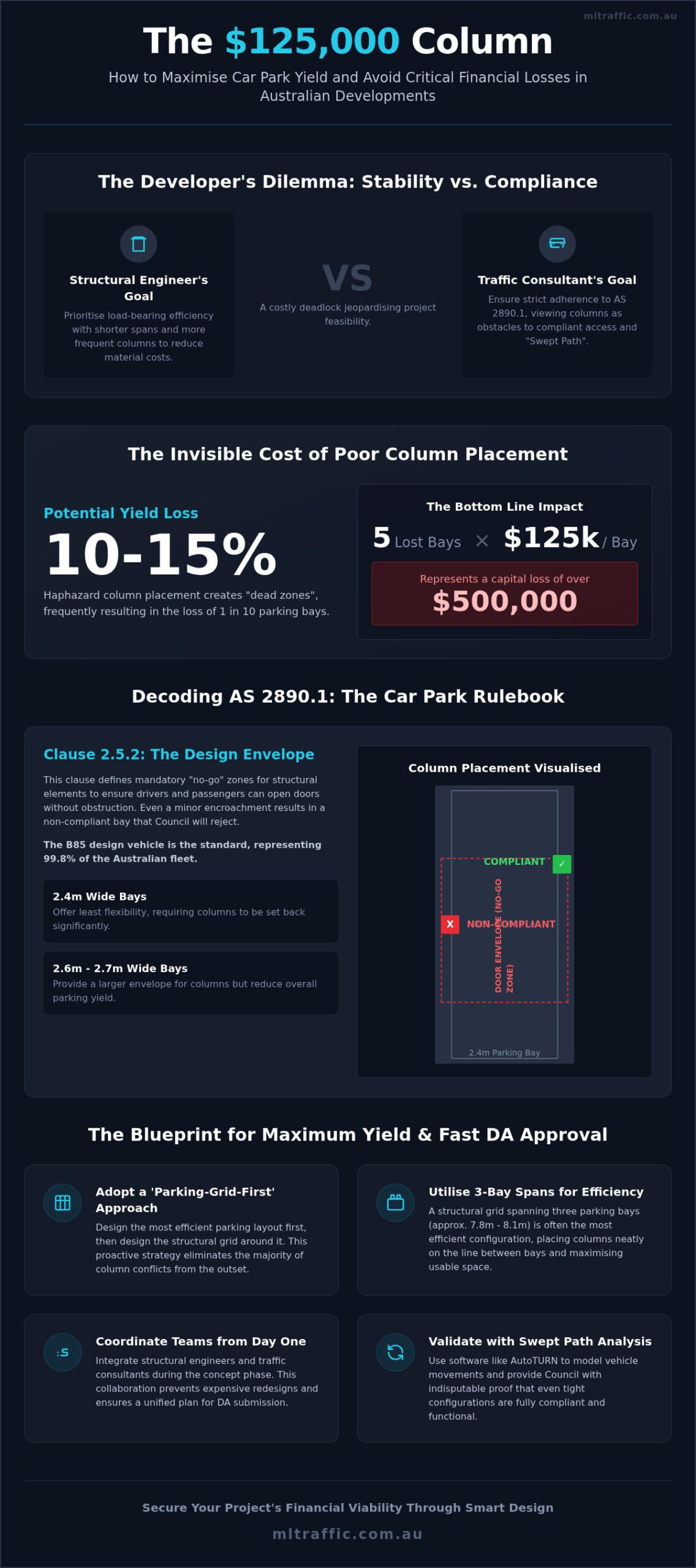
Parking yield is the ratio of usable bays to the total floor area of the car park. A report from the Grattan Institute (May 2026) estimates that basement parking costs in Australian capital cities can range from $55,000 to $125,000 per space. Losing just five spots due to poor column alignment represents a capital loss exceeding $500,000. For residential projects, under-parked developments face slower sales and lower valuations because they fail to meet buyer expectations or minimum statutory ratios. In commercial settings, insufficient parking leads to lower occupancy rates and reduced rental premiums for retail or office spaces.
Structural Integrity vs. Traffic Flow: The Developer’s Dilemma
Structural engineers typically prioritise load-bearing efficiency. They often favour shorter spans and more frequent columns to reduce material requirements. However, traffic consultants view these columns as obstacles to “Swept Path” compliance. Optimising the structural column placement impact on parking efficiency during the concept phase prevents these conflicting requirements from stalling a project.
Early-stage coordination is the only way to avoid expensive redesigns. ML Traffic Engineers provides specialised Car Park Design services to mediate between structural necessity and parking yield. Our approach ensures that column grids align with the B85 vehicle dimensions required by Australian Standards, securing both structural stability and maximum bay counts. This proactive alignment is essential for securing DA approval without the need for multiple, costly revisions.
Navigating AS 2890.1: The Design Envelope and Column Clearance
Adherence to AS 2890.1 is mandatory for securing Council approval in any Australian jurisdiction. Clause 2.5.2 specifically outlines the “no-go” zones where structural supports must not encroach. The structural column placement impact on parking efficiency is most apparent here; even a minor deviation from these mandated clearances results in a non-compliant bay that Council will reject. The standard establishes a design envelope around the vehicle to ensure safe access and egress for both the car and its occupants.
The B85 Vehicle and Door Opening Clearances
The B85 vehicle serves as the benchmark for 99.8% of the Australian vehicle fleet. Its physical dimensions dictate the minimum clearances required for door openings. The middle portion of a parking stall, typically between 1.25 metres and 3.75 metres from the aisle, is the most sensitive area for column placement. Within this zone, columns must sit far enough back to allow doors to open without obstruction. The allowed envelope changes based on bay width:
- 2.4-metre bays: These offer the least flexibility, requiring columns to be set back significantly to maintain compliance.
- 2.6 to 2.7-metre bays: These wider stalls provide a larger envelope for structural engineers but inevitably reduce the total parking yield.
- Front and Rear Zones: Columns placed at the very front or rear of the stall are subject to more lenient clearance rules because they sit outside the primary door-swing area.
Common Column Placement Pitfalls in Basement Designs
Developers often encounter compliance failures when columns are placed near blind aisles or tight turn-in circles. If a column sits too close to a driveway ramp or a kerb, it can impede the vehicle’s swept path. A critical factor to monitor is the “150mm rule.” A shift of just 150mm during the structural mark-up phase can move a column from a compliant position into the prohibited design envelope. This minor oversight renders the entire bay useless for DA reporting purposes.
Avoiding these pitfalls requires a meticulous review of structural plans against traffic standards. You can ensure your layout remains compliant by engaging a specialist for a Car Park Design review before submitting your DA. This proactive step prevents the need for retrospective structural changes that are both difficult and expensive to implement once the design is finalised.
Optimising Column Grids: Maximising Parking Yield vs Structural Needs
The structural column placement impact on parking efficiency is most manageable when developers adopt a “Parking-Grid-First” design philosophy. This approach involves establishing the car park layout before finalising the structural levels above. When the basement is treated as an afterthought, column positions are dictated by residential walls or commercial partitions, leading to irregular spans. These irregularities often result in “dead zones” or non-compliant bays that Council will not recognise in a DA. By prioritising the parking grid, you ensure the basement footprint is fully utilised for yield before structural loads are resolved.
Vertical alignment is another critical factor in protecting car park efficiency. In many multi-level developments, the use of transfer slabs allows for a cleaner basement grid. While transfer slabs add to the initial construction cost, they prevent columns from landing in the middle of parking stalls or access aisles. This strategic shift ensures that every square metre of excavated space contributes to the project’s parking count and overall feasibility.
The 3-Bay Standard: Why 7.5m to 8.4m Spans are King
A 3-bay span is the industry benchmark for basement efficiency in Australia. Spacing columns between 7.5 metres and 8.4 metres allows for three standard parking bays to fit comfortably between structural supports. This configuration offers several advantages:
- Maximised Yield: It minimises the “column-to-bay” ratio, ensuring fewer obstructions per parking spot.
- Improved Visibility: Reducing the total number of columns increases driver sightlines, which is a key safety requirement for Council approval.
- Service Integration: Wider spans provide more room to route pipes, ducts, and cable trays around columns without encroaching on the mandatory clearance envelopes.
While wider spans may require thicker slabs or post-tensioning, the value of the gained parking spots usually outweighs the additional material costs. A layout with fewer columns is also easier for drivers to navigate, reducing the risk of vehicle damage and long-term maintenance issues.
Managing Residential Grids in a Basement Environment
Residential developments present a unique challenge due to the fundamental conflict between 600mm apartment wall placements and 2.5m parking bay widths. If structural columns are carried straight down from the levels above, they rarely align with an efficient parking layout. Strategies for “shifting” or “walking” columns at the ground floor level are essential to clear basement bays. This coordination ensures that structural integrity is maintained without sacrificing compliant parking. For a deeper technical breakdown of these requirements, refer to our guide on AS 2890.1 Explained.
Beyond the Standards: Using Swept Path Analysis to Solve Column Conflicts
Vehicle Swept Path Analysis is the definitive technical method for resolving conflicts between load-bearing structures and parking functionality. While AS 2890.1 provides a prescriptive framework, the structural column placement impact on parking efficiency often requires a performance-based solution. This is especially true when a column must sit within a technically prohibited zone to support the levels above. We use AutoTURN Pro 2026 software to simulate vehicle movements in three dimensions, proving that a layout remains functional even when clearances appear tight on a 2D plan.
This analysis allows us to justify non-standard column placements by demonstrating that the B85 design vehicle can safely enter and exit every bay. We don’t just test the standard car; we also simulate larger B99 vehicles and Small Rigid Vehicles (SRVs) for loading zones. This empirical data provides Council assessors with the assurance they need to approve a design that might otherwise be rejected for failing a literal interpretation of the Standard’s clearance envelopes.
Proving Manoeuvrability in Tight Basement Corners
A column positioned on a corner drastically alters the turn-in radius for adjacent bays. Wide structural piers can also create blind spots that compromise safety. Our analysis visualises these movements, identifying exactly where a vehicle’s body or mirrors might come into conflict with the structure. For a comprehensive look at how this technology secures project viability, read our Swept Path Analysis: A Developer’s Guide. Identifying these conflicts during the design phase allows for minor structural adjustments that save thousands in retrospective redesign costs.
Negotiating with Council Using Technical Data
Council rejections are often based on perceived difficulty rather than actual vehicle physics. When an assessor sees a column near a turn-in circle, their default response is often a Request for Further Information (RFI) or a flat rejection. We counter this by presenting detailed Swept Path Diagrams as evidence within a Traffic Impact Assessment (TIA). By including 300mm clearance buffers in our simulations, we satisfy safety-conscious assessors and prove the car park is navigable for drivers of all skill levels. This data-driven approach removes subjectivity from the approval process.
Request a professional Vehicle Swept Path Analysis to validate your basement layout and secure your parking yield before submitting to Council.
Coordinating Structural and Traffic Engineering for DA Success
Coordination between structural and traffic disciplines is the most overlooked phase of basement design. Developers frequently wait until the structural grid is finalised before engaging a traffic consultant. This sequence is counterproductive. It forces the traffic engineer to work around fixed obstacles rather than influencing their placement for maximum yield. The structural column placement impact on parking efficiency is most positive when these two disciplines collaborate during the concept stage. A Traffic Impact Assessment (TIA) Report, reviewed by our senior principals, then serves as the formal documentation of this successful coordination. It provides Council with a clear, evidence-based rationale for the proposed layout.
The Early-Involvement Advantage
Reviewing the concept design before the DA is lodged saves thousands in redesign fees. Identifying a single column clash on paper is significantly cheaper than revising structural plans after an RFI from Council. We recommend a preliminary layout review to ensure the column grid aligns with parking requirements from the outset. You can Contact ML Traffic Engineers for an initial assessment of your current plans. This early feedback prevents the “dead zones” mentioned in previous sections and ensures every bay is technically compliant before you commit to a structural strategy.
Once the structural engineer provides their mark-ups, we perform a final cross-check against the parking layout. This step verifies that the load-bearing elements don’t encroach on the design envelope or obstruct vehicle paths. Final certification is equally important. Council requires the as-built columns to match the approved plans exactly. Any deviation during construction can lead to a refusal of the Occupation Certificate if the resulting bays no longer meet Australian Standards. With over 15 years of experience, we ensure the transition from paper to concrete is seamless.
Checklist for a Compliant and Efficient Car Park Layout
Use this checklist to evaluate your basement layout before submission:
- Confirm all columns sit outside the mandatory Design Envelope as per Clause 2.5.2 of AS 2890.1.
- Verify that “blind” aisles have adequate turning space for the B85 vehicle to exit in a single manoeuvre.
- Check that column placement doesn’t obstruct sightlines at the driveway or internal pedestrian crossings.
- Ensure that fire services and drainage pipes are integrated without reducing the vertical or horizontal clearances of the bays.
- Validate that the column positions don’t impede the swept paths of waste collection or delivery vehicles.
Meticulous attention to these details during the design phase eliminates the risk of expensive DA rejections. By treating the structural column placement impact on parking efficiency as a priority rather than an afterthought, you protect your project’s yield and ensure a faster path to approval.
Secure Your Parking Yield and DA Approval
Strategic design transforms the basement from a structural necessity into a high-yield asset. By prioritising the parking grid and ensuring columns sit outside the mandatory design envelopes defined in AS 2890.1, developers avoid the common 10% to 15% loss in parking capacity. Understanding the structural column placement impact on parking efficiency allows for a more streamlined DA process. It prevents the costly redesigns often associated with Council rejections and RFI delays during the planning phase.
Early coordination between your structural and traffic teams is essential to resolve clearance conflicts before they reach the building site. ML Traffic Engineers brings over 15 years of experience in Australian car park design to every project. We provide specialised AutoTURN Swept Path Analysis for complex sites and ensure direct senior principal involvement in every DA report. This meticulous approach ensures your car park layout is both compliant and commercially optimised for your next development.
Taking control of your basement design today ensures a more profitable and compliant development tomorrow.
Frequently Asked Questions
How do structural columns affect the number of parking spaces I can fit?
Columns create physical obstructions that dictate the width and length of usable bays. If columns are placed haphazardly, they create “dead zones” that cannot accommodate a B85 vehicle. This structural column placement impact on parking efficiency often results in a 10% to 15% reduction in total yield. Precise alignment is required to ensure columns sit outside the mandatory design envelope while supporting the structural load of the levels above.
What is the minimum clearance required between a column and a parking bay?
Clearance is governed by the design envelope specified in Clause 2.5.2 of AS 2890.1. Columns must generally be set back 0.25 metres to 1.25 metres from the aisle, depending on the bay’s position and the vehicle’s door-opening requirements. Placing a column within the middle section of a bay requires specific setbacks to allow for passenger access. Failure to maintain these clearances renders the bay non-compliant for DA purposes.
Can a column be placed within a parking space under AS 2890.1?
Structural columns are permitted within the footprint of a parking space provided they remain outside the prohibited design envelope. The standard defines specific zones where structural supports cannot interfere with vehicle doors or bodywork. Columns are most commonly placed at the front or rear of the stall, between 0 and 1.25 metres from the aisle, or beyond the 3.75-metre mark. These positions are less likely to obstruct door swings.
What happens if my columns shift during construction and no longer comply?
Any deviation from the approved plans during construction can lead to a refusal of the Occupation Certificate. If as-built columns encroach on the design envelope, the affected bays become technically non-compliant. This often requires expensive retrospective structural modifications or a permanent reduction in the legal parking count. We recommend regular site inspections to ensure the physical build matches the approved Car Park Design and Swept Path Analysis exactly.
How does Swept Path Analysis help with column placement issues?
Swept Path Analysis provides empirical proof that a vehicle can safely navigate around structural supports. Using AutoTURN software, we simulate real-world vehicle movements to validate tight layouts that might technically fail prescriptive standards. This performance-based solution allows developers to justify column positions to Council. We demonstrate that the B85 design vehicle maintains adequate clearance buffers throughout its entire turn-in and exit manoeuvre, removing subjectivity from the assessment.
Is there a standard column grid that works best for Australian car parks?
A 3-bay grid with spans between 7.5 metres and 8.4 metres is the most efficient configuration for Australian developments. This spacing allows three standard bays to fit between columns without encroaching on the prohibited zones defined by AS 2890.1. While 2-bay spans are common in residential structures, they significantly increase the number of columns and reduce overall visibility. Standardising the grid early ensures the basement footprint is fully utilised for maximum parking yield.
Does Council check column placement during the DA process?
Council assessors meticulously review parking layouts against Australian Standards during the Development Application phase. Any column that overlaps with the mandatory design envelope or obstructs a swept path will likely trigger a Request for Further Information (RFI) or a flat rejection. Providing a professionally certified Traffic Impact Assessment (TIA) that addresses structural column placement impact on parking efficiency is the most effective way to fast-track approval and avoid costly redesigns.
How can I maximise yield if my structural engineer needs more columns?
Maximising yield requires early coordination between the structural engineer and the traffic consultant. If additional columns are necessary for load-bearing stability, we use transfer slabs or “walked” columns to shift these supports into non-prohibited zones. Strategic placement at the corners of bays or within the front 1.25 metres of the stall can accommodate extra supports without losing compliant spaces. This proactive approach ensures structural necessity doesn’t compromise the financial feasibility of the project.

Disclaimer
The content on www.mltraffic.com.au, including all technical articles, guides, and resources, is provided for general informational and educational purposes only. It is not intended to constitute professional advice in traffic engineering, transportation planning, development approvals, or any other technical or legal field.
While ML Traffic Engineers makes every reasonable effort to ensure the accuracy, completeness, and timeliness of the information published, we do not provide any warranties or representations (express or implied) regarding its reliability, suitability, or availability for any particular purpose. Any reliance you place on the content is strictly at your own risk.
In no event shall ML Traffic Engineers, its directors, employees, authors, or affiliates be liable for any direct, indirect, incidental, special, consequential, or punitive damages (including, without limitation, loss of profits, data, or business opportunities) arising out of or in connection with the use of, or inability to use, any information provided on this website.
The articles and guides on this site are not a substitute for engaging a qualified, registered professional traffic engineer (such as an NPER or RPEQ engineer) to assess your specific project requirements. For tailored advice, compliance assessments, or traffic engineering services, please contact a competent professional.
This disclaimer may be updated from time to time without notice. By accessing or using this website, you agree to be bound by the most current version of this disclaimer.
